Understanding the OSI Model
The Open Systems Interconnection (OSI) model is a conceptual framework that standardizes the functions of a telecommunication or computing system into seven abstraction layers. This paper explores each layer in detail, illustrates the flow of data through various network devices, explains how data is encapsulated at each layer, and compares the OSI model with the TCP/IP suite. The inclusion of diagrams provides visual representations to enhance understanding.
Introduction
In the rapidly evolving world of computer networks, understanding how data travels from one device to another is crucial. The OSI model serves as a foundational blueprint that guides this understanding by dividing the networking process into seven distinct layers. Each layer has specific responsibilities, ensuring that data is transmitted accurately and efficiently across networks. This paper delves into the intricacies of the OSI model, incorporating visual aids to elucidate complex concepts.
The OSI Model Explained
The OSI model comprises seven layers, each building upon the last to facilitate seamless communication:
- Physical Layer (Layer 1): Manages the physical connection between devices, including cables, switches, and signal transmission.
- Data Link Layer (Layer 2): Ensures error-free data transfer between adjacent network nodes through error detection and correction.
- Network Layer (Layer 3): Handles data routing, forwarding, and addressing to enable data transmission between devices on different networks.
- Transport Layer (Layer 4): Provides reliable data transfer services to the upper layers, including flow control and error handling.
- Session Layer (Layer 5): Manages and controls the connections between computers, establishing, maintaining, and terminating communication sessions.
- Presentation Layer (Layer 6): Translates data between the application layer and the network format, handling data encryption and decryption.
- Application Layer (Layer 7): Closest to the end-user, this layer interacts with software applications to implement a communicating component.
Data Flow Through Network Devices
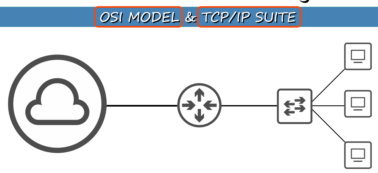
This diagram illustrates how data flows from a cloud-based service through various network devices before reaching end-user devices.
The journey includes:
- Cloud-Based Service (Internet): Data originates from services hosted on the internet.
- Routers: Operate at the Network Layer (Layer 3), directing data packets based on IP addresses to their destination networks.
- Switches: Function at the Data Link Layer (Layer 2), forwarding data frames within the same network segment using MAC addresses.
- End-User Devices: Devices like computers or smartphones that receive the data for user interaction.
The diagram demonstrates the practical application of the OSI model and the TCP/IP suite, highlighting how each layer and device plays a role in data transmission.
Data Encapsulation and Protocol Data Units
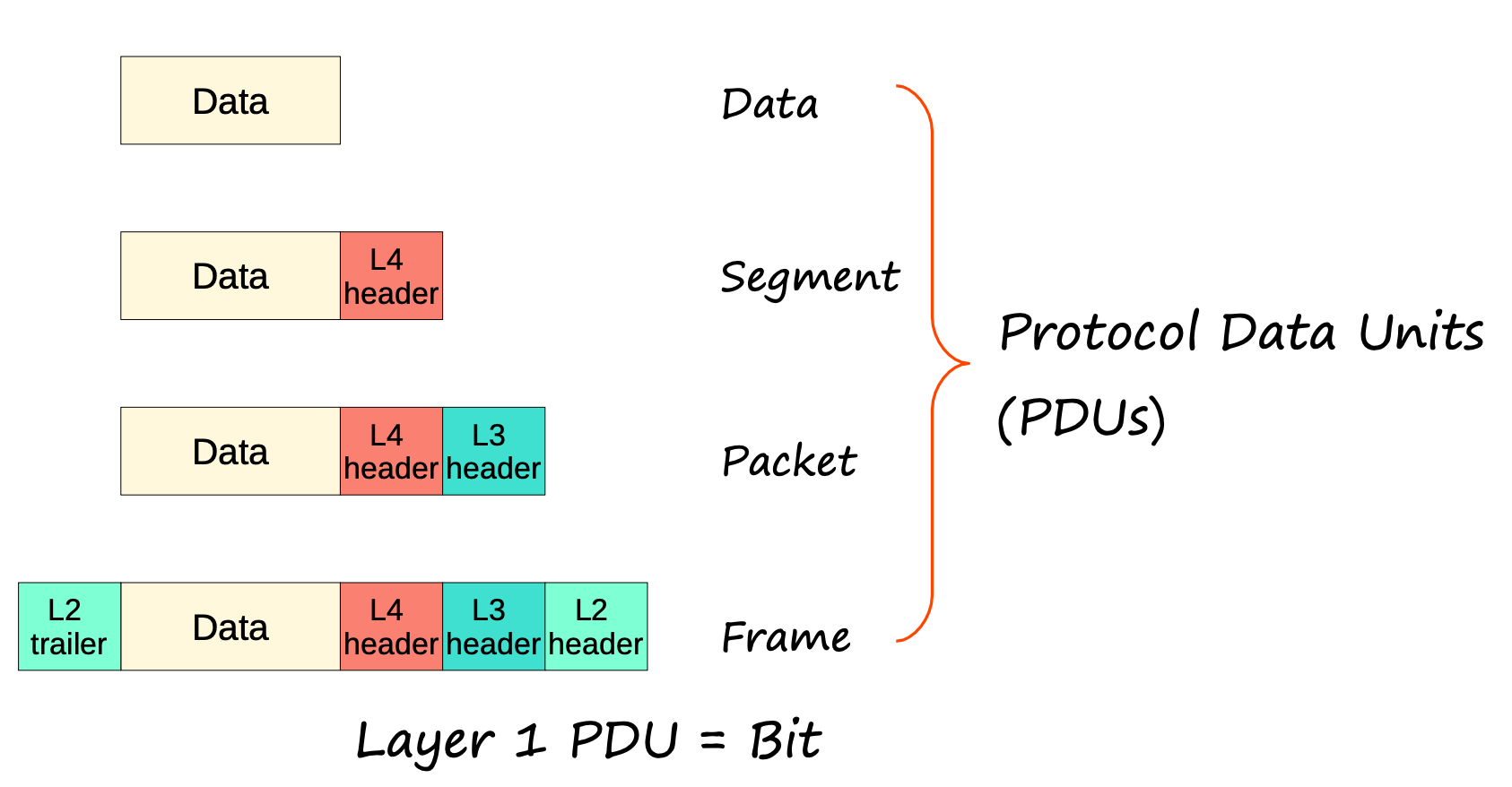
This image breaks down how data is encapsulated as it travels through each layer of the OSI model.
As data moves through the OSI layers, it undergoes encapsulation, where each layer adds its own header (and sometimes a trailer) to the data unit from the layer above:
- Application, Presentation, Session Layers (Layers 7-5): Data starts as high-level information.
- Transport Layer (Layer 4): Encapsulates data into Segments, adding headers containing source and destination port numbers.
- Network Layer (Layer 3): Segments become Packets with the addition of IP headers that include source and destination IP addresses.
- Data Link Layer (Layer 2): Packets are framed into Frames with headers and trailers containing MAC addresses and error-checking data.
- Physical Layer (Layer 1): Frames are converted into a stream of Bits for transmission over the physical medium.
This process ensures that each layer can properly interpret and handle the data it receives.
Comparing OSI and TCP/IP Models
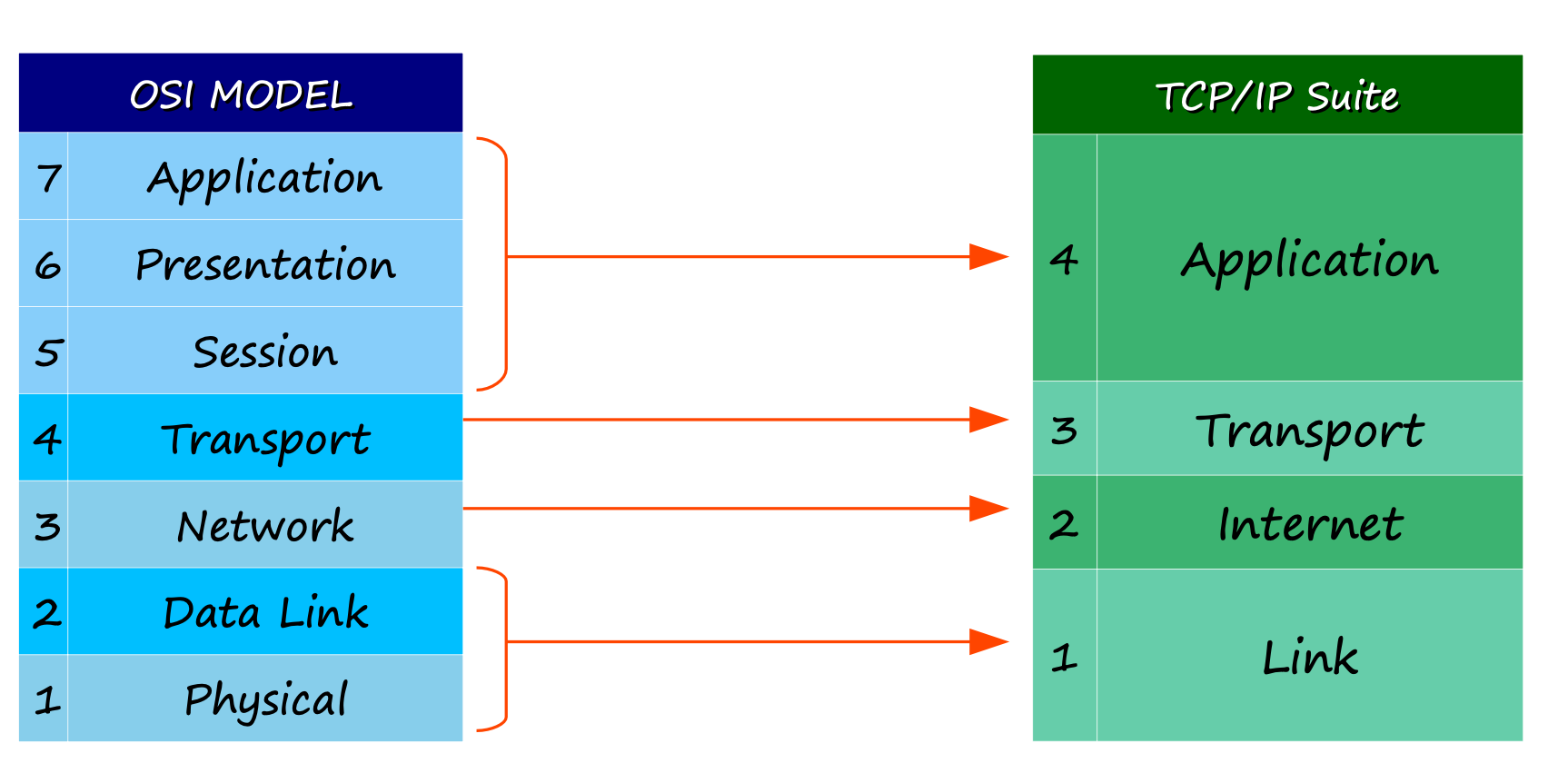
This comparative chart maps the seven-layer OSI model against the four-layer TCP/IP suite.
The TCP/IP suite simplifies the OSI model’s seven layers into four:
- Application Layer (TCP/IP): Merges the OSI’s Application, Presentation, and Session layers.
- Transport Layer (TCP/IP): Corresponds directly with the OSI’s Transport Layer.
- Internet Layer (TCP/IP): Aligns with the OSI’s Network Layer.
- Link Layer (TCP/IP): Combines the OSI’s Data Link and Physical layers.
This mapping clarifies the functions each model handles and underscores their interoperability. Understanding this alignment is essential for network professionals who work with both models.
Practical Application of the OSI Model
The OSI model isn’t just theoretical; it has practical implications in real-world networking:
- Troubleshooting: By isolating issues to specific layers, network engineers can efficiently diagnose and fix problems.
- Protocol Development: Helps in designing protocols that can interact seamlessly across different systems and devices.
- Education: Provides a structured approach to teaching and understanding complex networking concepts.
Conclusion
The OSI model remains a cornerstone in the field of networking, offering a universal language to describe how data moves across a network. By breaking down the communication process into manageable layers, it simplifies the complexities inherent in network interactions. Comparing it with the TCP/IP model further enhances our understanding of networking protocols and their practical applications. The diagrams included reinforce these concepts, providing visual clarity to the intricate processes involved.
References
- Stallings, W. (2017). Data and Computer Communications. Pearson.
- Tanenbaum, A. S., & Wetherall, D. J. (2010). Computer Networks. Prentice Hall.
Enjoy Reading This Article?
Here are some more articles you might like to read next: